Free Space, SMA 905, FC: Fiber connections in spectroscopy
Spectrometers can be used to test and determine a wide variety of samples. Electromagnetic radiation, i.e. visible light, but also UV or NIR radiation, is directed at the object of interest and some of the emitted wave positions interact with its matter. The energy of precisely these photons then causes a molecule to vibrate, for example. Exactly this energy will then be missing in the radiation that a spectrometer subsequently records. The missing spectral components are not random, but are characteristic of certain substances. This allows you to determine not only what kind of material you have in front of you, but often also how much of which substance is present in the sample. Good measurement results require good signal quality: as much radiation as possible must reach the spectrometer and as little interference as possible must distort the signal. Of course, the quality of the spectrometer itself also plays an important role here: a high signal-to-noise ratio is also essential when converting the analog radiation signal into digitally usable data.
However, the spectrometer often cannot be placed directly at the point of interest.There can be many reasons for this. Perhaps there is not enough space at the measuring point, or, especially in industrial production, the immediate vicinity is too harsh, having strong vibrations, high temperatures, etc.
In these cases, the signal is often captured with lenses, which then transport it to the spectrometer via an optical fiber. Signal losses will occur at every transition in this chain. If precision is required, it is therefore worth taking a closer look at these steps in the signal processing chain - and in particular at their connection points.
Coupling losses - an unavoidable problem?
A very important factor here is that the fibers are practically never perfectly aligned with each other. A fiber cross-section of 600 µm is already one of the heavyweights in spectrometry, 400 µm or even 200 µm are not uncommon. Even a deviation of 0.05 mm would therefore have a considerable impact.
In addition, there are optical factors: there is a material transition from fiber to air and back to fiber, and this leads to refraction and possibly even reflection, which can deflect parts of the signal. And in practice, the surfaces of the fiber ends themselves will not be perfect. Firstly, because production itself reaches its practical limits at some point. In addition, scratches can always occur in practice when the fibers are connected to each other via connectors.
Depending on the fiber and connector, each of these transitions can lead to losses of over 1 dB, i.e. around 30% of the input signal.
Free Space: Coupling without any connectors
The best connector is therefore the one that is saved. In the so-called free space connection, there is no fiber or connector at all. Instead, the radiation is guided to the input of the spectrometer using optical components such as lenses. On the way, the beams only pass through air or, in rare special cases, even a vacuum.
A free-space connection undisputedly offers the potentially highest coupling efficiency. However, this potential comes at the cost of the need for careful alignment of the beam, and thus a correspondingly precise mechanism. Free-space connections are therefore fundamentally more susceptible to vibrations and other mechanical shocks. In addition, this structure can be more sensitive to external light influences from the environment, because the beam is not guided within a fiber and therefore lacks its cladding.
Glass fibers themselves can be limiting for a measurement scenario in different ways. One example is very strong light sources that reach intensities that can damage the material of the fiber itself. In a free-space setup, it is possible to work with such intensities because the fiber has been taken out of the equation as a limiting factor.
The situation is very similar if the same optical structure is to be able to process a very broad spectrum of wavelengths, for example from UV to mid-infrared. The materials available for glass fibers are not yet able to conduct equally well at all these wavelengths. Fibers that conduct particularly well in the short-wave range (e.g. from 200 nm to 1200 nm) absorb too much of the signal at higher wavelengths. There are therefore special fibers for the NIR range - which in turn absorb strongly in the short-wave range. If this cannot be solved by using multiple fibers, the only remaining option is the free-space connection.
The susceptibility of the free-space connection to external mechanical and radiation influences usually weighs too heavily for industrial test scenarios. However, they can shine in the laboratory, where these environmental factors can be better controlled.
F-SMA: The classic among fiber optic connectors
If the signal from the sample is to reach the spectrometer via fiber and connector, then you immediately come across the classic: F-SMA or SMA 905.
SMA (Sub-Miniature Assembly) is already a proud six decades old: it was designed back in the 1960s, but at that time for coaxial cables, i.e. electrical connections with copper wire instead of fiber optics.
At the end of the 1970s, Amphenol developed a version for fiber optic cables based on SMA and called it F-SMA (Fiber Sub-Miniature Assembly). There are two versions of F-SMA for different fiber diameters, SMA 905 and SMA 906. In fact, only SMA 905 is used for spectrometers and other sensors because SMA 906 is intended for wide, more cost-effective fibers and spectroscopy is usually all about the maximum quality of the signal.
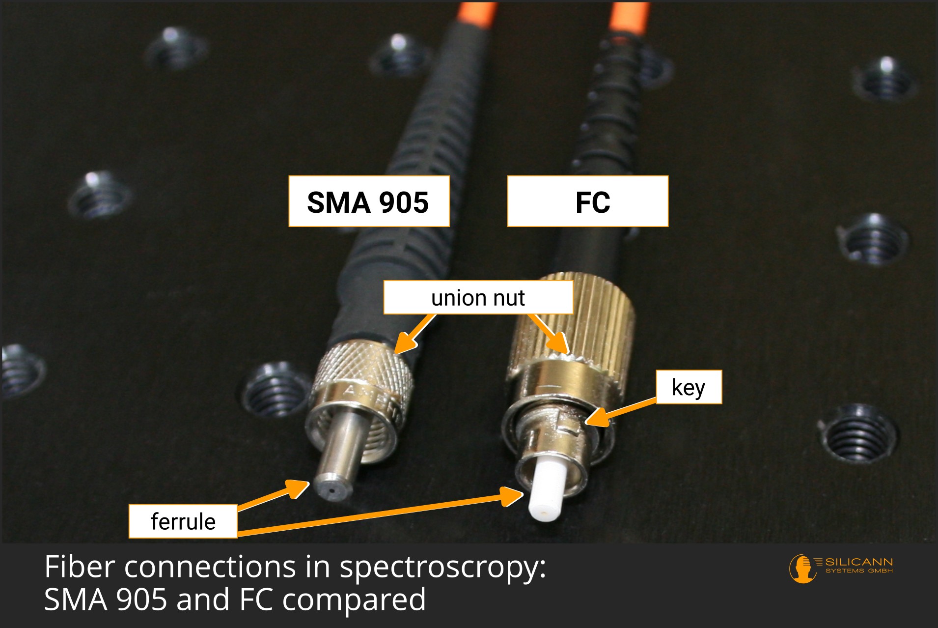
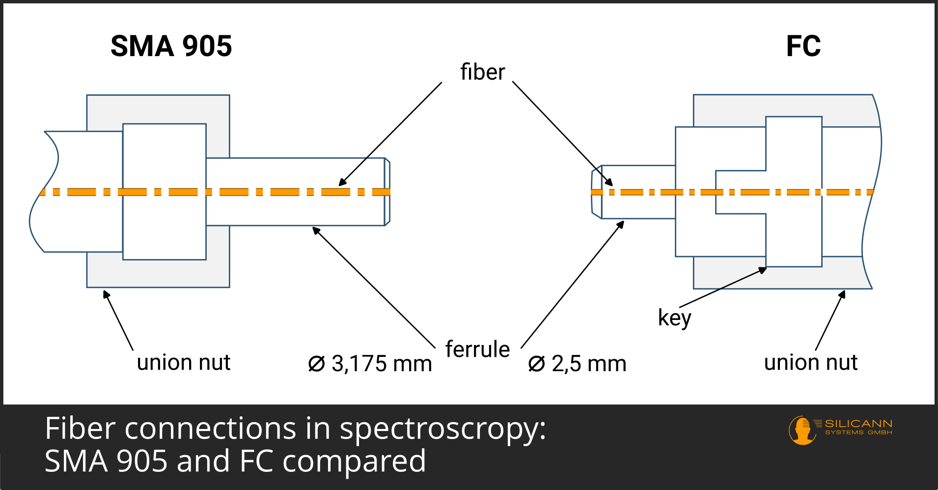
With SMA 905, the fiber is firmly inserted into a ferrule, which is then screwed to the socket using a union nut.
SMA is a very robust connector and this is probably one of the reasons why it has lasted so long in measurement technology and spectrometry, while new connectors have long since found their way into, for example, the telecommunications sector.
Even today, the SMA 905 is still the most widely used connector in spectrometry. In addition to its actual mechanical robustness and high tolerance to vibrations and temperature fluctuations, this is certainly also due to the fact that automation technology in particular is often quite slow-moving. People are reluctant to shake up established procedures, and once integrated, measuring devices should be able to withstand the production process for many years.
However, there is also something to be said for the search for an alternative connection of fiber optic cable and spectrometer: the rather high insertion loss in the F-SMA connection, i.e. the coupling losses at the transition from plug to socket. This is due to the limitation that normal SMA connections are not torsion-proof. At the moment of fixing, the ferrule in the connector can therefore rotate slightly and may therefore not fit perfectly on its counterpart. Due to the design of SMA, the ferrules can touch each other, but a clean physical contact between the fiber ends cannot be established. There is therefore an air bridge and corresponding refractions at the material transition. The ability of the fibers to twist in relation to each other can also quickly lead to the surfaces of the fiber ends becoming scratched due to dirt on the SMA connector.
Insertion losses of around 1 dB are common with SMA connections - this means that almost 26% of the signal is lost per SMA coupling.
Insertion loss and back reflection - the major sources of loss in fiber connections
The two main problems when connecting optical fibers are insertion loss or coupling loss and back reflection.
Insertion loss
Insertion loss refers to the power loss that occurs when one fiber is coupled to another. Beams emerge from the first fiber, but in some cases do not enter the second fiber at all or not at a suitable angle, so that they can no longer be detected by the spectrometer. The main reasons for this are a too imprecise alignment of the fiber ends to each other or a no longer completely flat surface of the fiber end, which inevitably happens over time due to scratches caused by everyday use. The insertion loss is specified in dB, i.e. in a logarithmic measure. Accordingly, an insertion loss of 3 dB means that 50 % of the input power is lost, at 1 dB it would be 29 % and at 0.3 dB around 7 %.
Back reflection
Back reflection describes the situation where the radiation does not exit the fiber end to re-enter the next fiber, but is instead reflected on the inside of the fiber end and guided back to the origin. This is usually undesirable, as these waves are now superimposed on the actual signal, leading to interference and noise. In addition, the reflected part no longer reaches the spectrometer, so the signal is weaker overall.
FC connector - how does the ferrule connector compare?
At first glance, SMA and FC connectors are very similar. The Ferrule Connector also has a cylindrical ferrule that is fixed in place with a union nut. However, in spectrometry at least, this ferrule is often made of ceramic instead of stainless steel.
However, some minor changes to the FC connector result in significantly lower insertion loss. Firstly, the ferrule is now spring-mounted. As a result, the fit of ferrule to ferrule no longer depends on the sensitivity of the person fixing it, because the force is no longer transferred to the fiber end as directly as with SMA. The contacting of the fiber ends is further improved by the fact that the FC connector also has a plug key that protects the ferrule from twisting. In combination, these two improvements mean that the ferrules can be assumed to be precisely aligned with each other. For this reason, other fiber end polishes are possible with FC than the completely flat finish with SMA. The standard specifies a slightly convex polish to ensure that the fiber ends actually physically touch each other. Unsurprisingly, this variant is also called Physical Contact (PC).
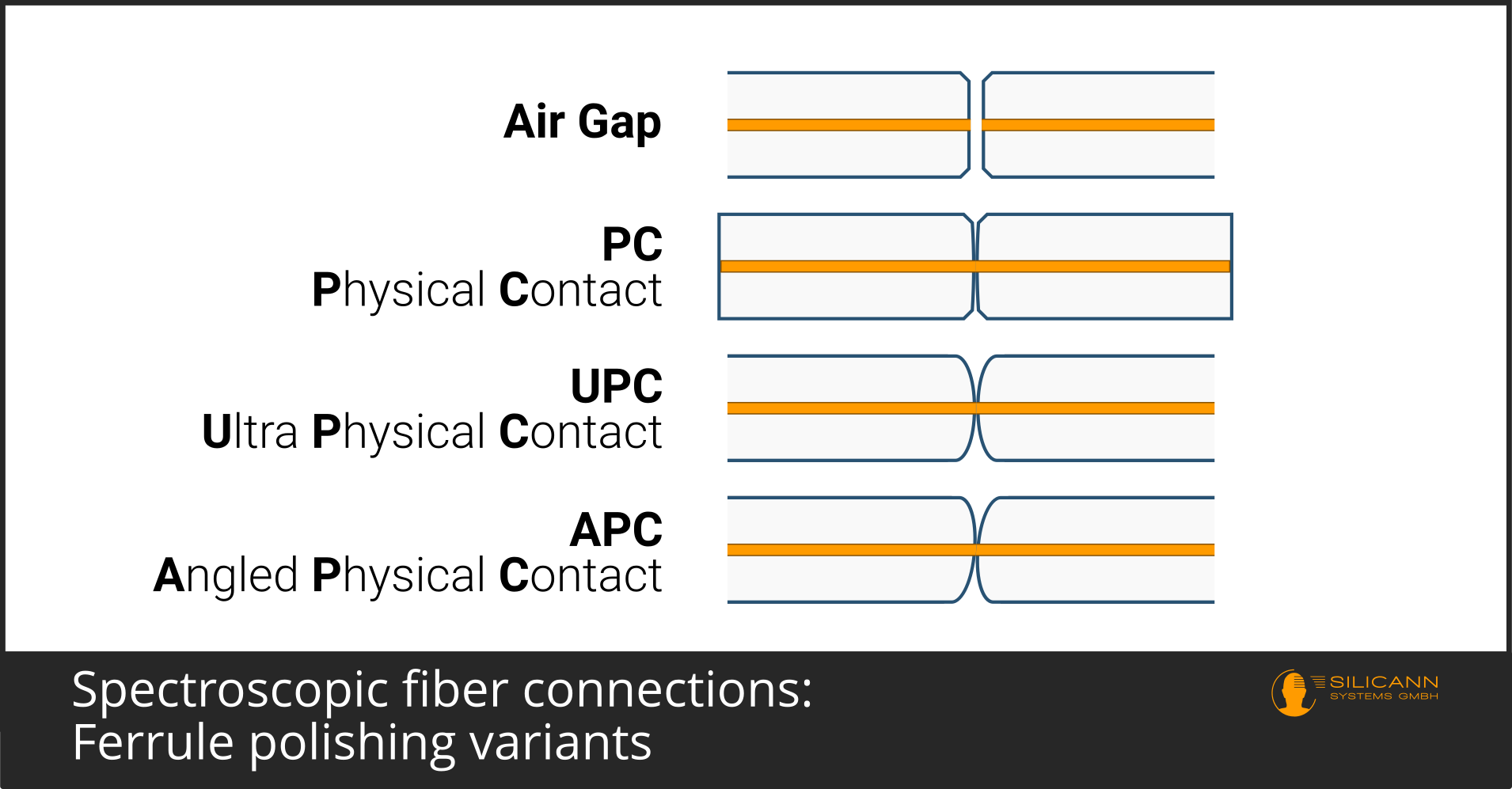
In addition to Physical Contact, there are also the variants Ultra Physical Contact (UPC) and Angled Physical Contact (APC) for even higher signal quality. Fibers of the Ultra Physical Contact grade are polished with a slightly higher crown than regular PC fibers. APC fibers are slightly crowned, too, but are also manufactured with an angle of 8°. Both UPC and APC enable slightly better signal transmission than the regular PC variant. In practice, these can be distinguished by their designations even without a magnifying glass. The connectors are usually described as FC/PC, FC/UPC and FC/APC. APC fibers often also have a green bend protection.
Because the FC fiber connector can have a significantly lower insertion loss with comparable robustness, it is expected to increasingly replace the SMA connector in process spectrometry.
You might also like

AI-Assisted Development for Spektralwerk Spectrometers
The Spektralwerk API documentation is now available as an MCP server. This facilitates AI-assisted development, particularly in security-conscious companies.