Color Sensors
There are many situations in industrial production where the scrutinising look of a skilled employee would be desirable. But in most settings this can’t be realized in an economically rational way. The inspection by a human would be ideal in cases where the end product will be highly visible for the customer and has to show consistently high quality. A typical case in demand of consistently high color reproduction over multiple batches: If a customer already bought 10 items of a particular product in a particular color, then a reorder ideally shouldn’t be optically distinguishable from the original batch. This establishes trust and ensures customer loyality in the future.
Color Sensors and Color Spaces
Automating this process is non-trivial because the human eye doesn’t perceive the electromagnetic spectrum of visible light in a neutral way. What we perceive as uniform colors in everyday situations is more often than not composed of different spectral color components (Isaac Newton first described this phenomenon we now call metamerism over 300 years ago. It took an additional 180 years to establish the fact that different receptors in the human eye are the cause for this).
It gets even more complicated once we have to handle distances between multiple colors. At the latest this is the moment where the limitations of simple red-green-blue sensors become a problem. The following diagram showing the different color sensitivities of the receptors of the human eye should illustrate the reason:
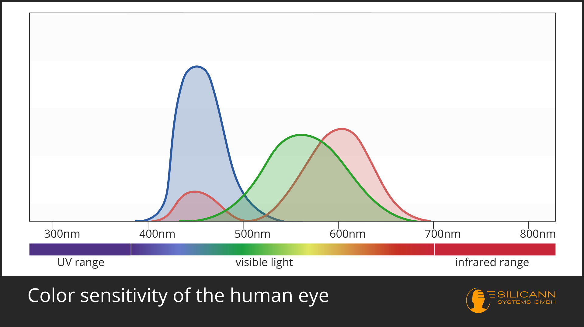
The receptors of the human eye process light stimuli with different sensitivity, depending on the spectral range of the stimulus. To further complicate things the overlap of the receptors is particularly bad around the 500nm range. We are nearly blind for narrow stimuli in that range!
If we want to reliably detect variances in automatic assembly, an RGB color sensor can develop into a potential source of errors very fast. The human eye is markedly less sensitive for variances between green and blue but quite sensitive for variances of red objects. If we want to define a range of tolerance around a reference value, we can’t just draw a circle around the reference, because the human eye would perceive a shift into the red range more easily than the same shift into cyan.
For automatic measurements this means the tolerance range around a reference can’t be defined with a constant size and form. That would either allow some products to pass the test while a human would perceive the variance, or the tolerance would be so narrow that products fail the test while a customer could not spot any difference between the failing item and the reference.
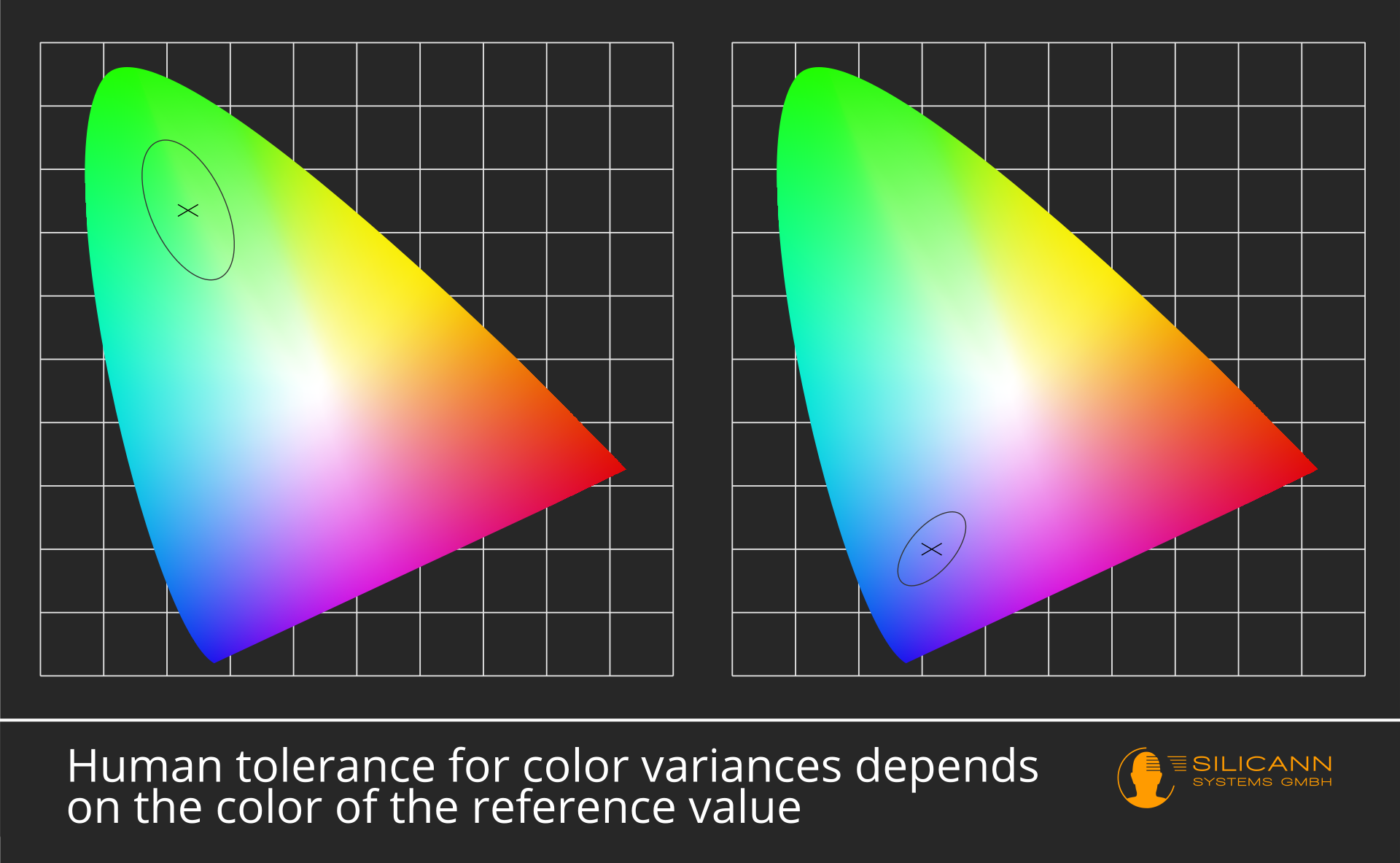
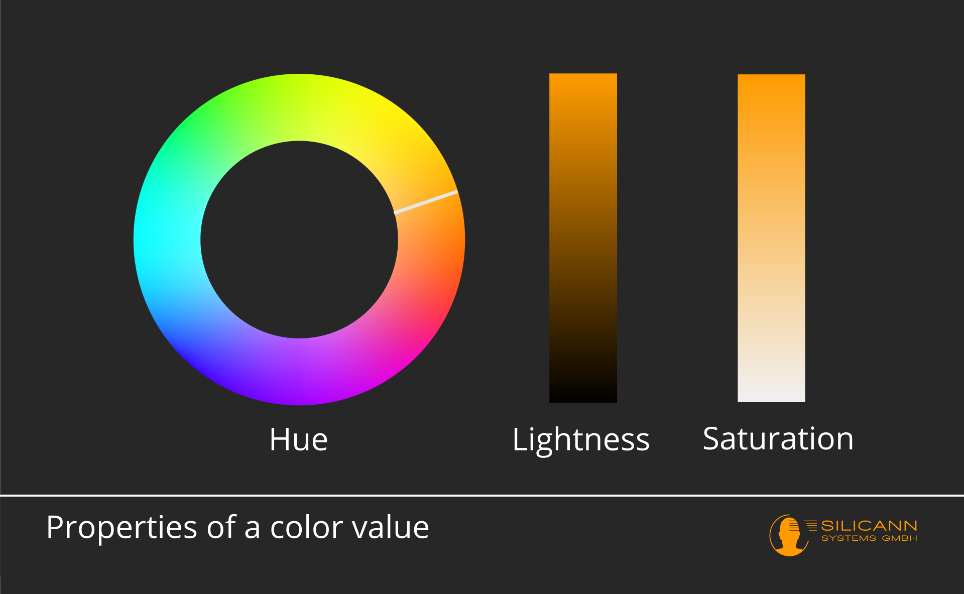
This problem is not cleanly solvable within the RGB color space. The challenge is mapping the spectrum of visible light into a color space so that equal distances within that space are perceived as equally large color nuances by human beings. Luckily researchers are working on that for nearly 100 years now. The result is the L*A*B* color space (sometimes also called LAB color space or CIELAB color space), wich still gets further refined. This color space satisfies the goal of perception-conformable color distances. It’s also standardized as an EN-ISO standard and gets further developed by CIE, an industry-independent institute.
Blickwerk color sensors support the L*A*B* color space, among others, so you an rely on them providing you clearly defined tolerances in your assembly processes.
ΔE - The Measurement of Color Distance
With a perception-conformable color space at hand, defining a measurement for the perceived distance between two arbitrary colors became possible. The result was ΔE or delta E (The E stems from the german word Empfindung, meaning perception). ΔE essentially describes the linear distance between two points in color space. There exist severeal further developments for ΔE (among others ΔE94 and ΔE00), all pursuing the goal of perfect representation of human perception of color distances as trigonometric distances in color space.
How to interpret a particular value for ΔE? The value can lie within 0 and 100. A color distance of 0 means we have two exactly identical colors, whereas a distance of 100 would imply maximum distance.
A good real-world reference is the border of human perceptibility. Jason Gibson conducted a study with about 30 subjects who had to grade differences between an original image and slight variations of said image, on different computer displays (“Colorimetric tolerances of various digital image displays” is the title of said study). The subjects had to decide whether they are looking at the original or a variation. The color properties hue, brightness and saturation were researched independently. The persons were intensively searching for differences, they weren’t just glancing at the pictures.
The results: The persons in the test batch could perceive differences in hue and saturation for distances of ΔE ~ 0.9 and more. Differences < 0.9 were perceived as identical. For distances purely originating in hue differences (imagine a rainbow-colored circle where a clockhand gets turned ever so slightly), the persons were even less sensible: Distances had to be between ΔE = 4 and ΔE = 6 to get recognized as differences.
Overall, the threshold of perceptibility for differences on computer displays lies between ΔE = 0.9 und ΔE = 6, depending on the nature of the color shift.
Color Sensors: Fast and Precise.
For comparison: Blickwerk color sensors can differentiate color distances as low as ΔE < 0.3. These are color nuances far below the threshold of human perceptibility. At the same time the Blickwerk range of color sensors offer sampling rates of up to 30 kHz. With these performance reserves you can be confident to archieve fast and precise real-world results even under suboptimal conditions like dark surfaces or variing object distances.
Secure Return on Investment
We set great value upon Silicann color sensors to ease your work, not aggravate it, now and in the years to come. That is the main reason why we implemented a uniform interface for the whole sensor range and will keep it stable for the whole lifetime of Blickwerk. Should you have integrated some Blickwerk 10 sensors into your assembly line and now want to upgrade or extend the installation with Blickwerk 20 or 40 color sensors, you can be sure to be greeted with identical interfaces for both the web-based controls and lower-level ports.
Blickwerk sensors can be integrated into your assembly processes through conventional and time-tested ports and interfaces. At the same time you have the option of cashing in on the networking promises of Industry 4.0: Without affecting the normal workload of the sensor you can e.g. save data about performance, failure rates etc. into your database or ERP environment, whether that is called SAP or Excel.
Beyond that the fiber optics interfaces are fully compatible among the whole range of Blickwerk color sensors and PCS color sensors. That way, you can select from a wide range of fibers and optics to solve exactly your problem - and be sure nothing about that changes in the coming years.
Wide Range of Glass Fibers and Optics
The color sensor is the place of signal processing. In a production setting one usually cannot place the sensor directly near the objects of interest without affecting other parts of the production line. Thanks to a wide selection of glass fibers in different configurations this isn’t needed anyway. Both object illumination and the transport of incoming signals can be physically separated from signal processing. This way, there only have to be few millimeters of space available at the point of inspection.
Glass Fibers for Silicann Color Sensors
Transmitted-light fibers or reflected-light fibers
Transmitted-light fibers are most suitable for translucent target objects. Typical examples are liquids, foils or gaseous mediums (e.g. a welding flame). The two separately encapsulated fiber bundles function both as the sending path for sensor-integrated light source and receiving path for incoming light transmitted to the sensor.
Reflected-light fibers are best suited for optically opaque target objects, especially solid surfaces. The evenly mixed fiber bundles transmit the light spectrum in both directions.
The glass fibers are available in different lengths and with different sheathings, fiber strengths and end pieces.
Possible fiber lengths and sheathing materials
Fiber optics, both transmitted-light fibers and reflected-light fibers, are suppliable in lengths from 20cm up to 240cm. If your environment requires other dimensions, custom lengths up to 30m are technically possible.
Depending on your specific working environment you can select from a multitude of different fiber sheathings .
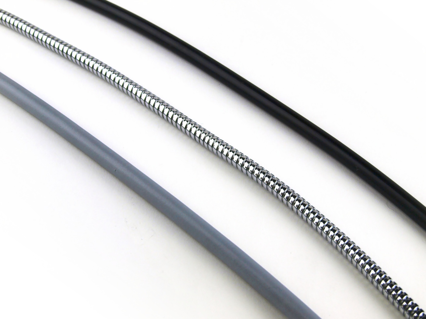
A silicon sheathing is advisable for applications where openly accessible liquids are to be inspected. Silicon sheathing is temperature stable for temperatures up to 180°C, liquid-tight and simultaneously very resistant against traction, kink and torsional forces.
The PVC sheathing delivers good protection against mechanical forces like pressure and traction while still providing a flexible optical fiber. Fibers with PVC sheathings are suitable for environmental temperatures up to 80°C.
With the metal sheathing variant the fiber is protected by a chrome-plated brazen spiral-hose. Optionally producing a variant in stainless steel is available. Using this sheathing is especially advisable for very high environmental temperatures as the stainless-steel sheathing is temperature stable for temperatures up to 400°C.
If you can’t find your particular situation in these examples please don’t hesitate to contact us regarding custom fiber optics variants. It’s quite possible that there exists a version for your exact environment, like sheathings with extra-high vibration protection or very small bending radii.
Cross sections, end pieces und connections of fiber-optic cables
Both for the transmitted-light fibers and the reflected-light fibers there a two different cross sections available: 1.5mm² and 2.5mm². Just like with electrical wires, the main advantage of a bigger cross section is the lower attenuation, i.e. the longer the distance between the sensor and the point of inspection, the more beneficial a higher optical fiber cross section.
Whether your actual use case is suited for a 1.5mm² fiber cross section should be worked out in a direct conversation, as bending radii, lighting and surface properties also play a role in that decision.
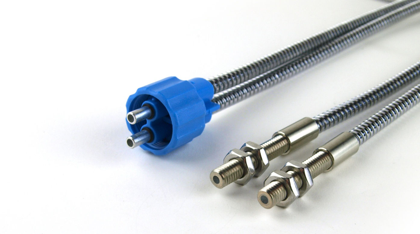
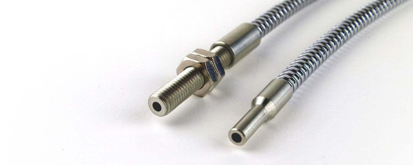
All optical fibers get connected to our color sensors with a M18x1 thread. They are fully compatible with both our PCS line and Blickwerk line of color sensors.
At the inspection side of these fibers the options are smooth end pieces and end pieces with M6 outside threading. This way, you have full flexibility when fastening the fiber near the point of inspection. Smooth end pieces are ideal for fastening with a grub screw. The threaded variant, especially in combination with a locknut, is the more robust way of fastening the fiber, but also needs a bit more space.
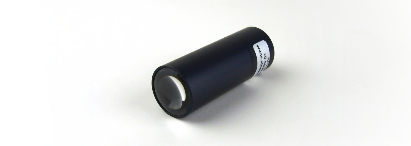
Optics for color sensors
Principally the color sensors are fully functional by only adding a fiber-optical cable. Using optics for targeted shaping of the measuring spot is completely optional. But sometimes the conditions at the production line make special demands on size or form of the measuring spot and minimum distance to the target objects.
For particularly small measuring spots Focus Optics KL-4 is the optics of choice. By using it, measuring spots as small as 0.6mm up to 3mm are realizable - as long as the target object distance is between 8 and 20mm. It is suitable both for transmitted-light fibers and reflected-light fibers.
Focus Optics KL-3 is also suited for measuring distances between 8mm and 20mm. This one is applicable if you need a measuring spot between 1mm and 5mm in diameter. KL-3 can be also be combined both with transmitted-light fibers and reflected-light fibers.

Because of the small object distance neither KL-4 nor KL-3 make particularly high demands on the object lighting. This also makes them suitable for darker target objects.
If you want to have bigger measuring spots (or your production line makes this a necessity without alternative) then other optics are becoming interesting. Focus Optics KL-M18-A2.0 is ideal for measuring distances from 15mm to 50mm. It creates measuring spot diameters between 2mm and 10mm.
For even higher measuring distances Focus Optics KL-14 and KL-34 come into play. Focus Optics KL-14 creates measuring spot diameters from 10mm to 20mm with distances between 60mm and 120mm. With a spot this big the sensor can only output data about general optical impressions. Specific surface details are hard to differentiate with these diameters as the sensor processes the whole measuring spot regardless of its size as a dimensionless point that gets compared to the reference value. Focus Optics KL-34 creates measuring spots of the same size, but at even greater distances of 80mm up to 150mm.
KL-34/62 is a variant that keeps the same measuring distance of up to 150mm. But focusing more it manages to create a small measuring spot of 2mm to 5mm in diameter. One pays a price for this relation of spot diameter and distance, though: In this scenario strong lighting at the point of inspection is advised. And you’ll got more precise results if you inspect lighter object surfaces.
Special solution: color sensor optics with gap-shaped measuring spot
For some applications the usual circular measuring spot is not ideal. Focus Optics KL-8 can strike up in these situations: It creates gap-shaped measuring spots with dimensions between 4x0.7mm and 30x5mm. The working distance has to be between 8mm and 20mm. With this ratio of spot diameter to distance you’ll get very fast and precise results even with dark surfaces and less than ideal lighting conditions.
Special solution: Color sensor optics for glossy or reflecting objects
Glossy or reflecting objects are particularly challenging when automatically inspecting colors. For precise measurements of the objects active lighting with a calibrated light source is required. This light source is integrated into the Silicann color sensors. The light gets transmitted through the optical fibers to the point of inspection. As the illuminated object should be inspected through the same fiber, reflections on a glossy object surface can quickly lead to problems.
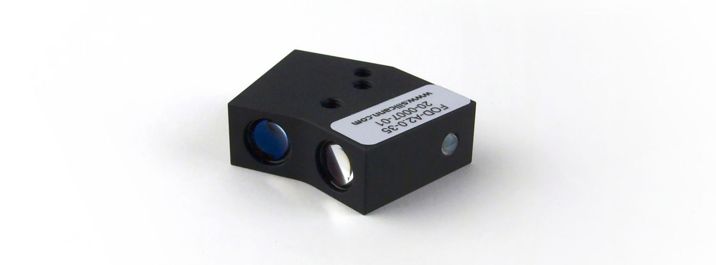
One solution are special optics that guide illumination to and measurements from the objects in different angles, thereby preventing reflections to occlude a precise measurement. Focus optics FOD-A2.0-35 and FOD-A2.0-100 implement this approach.
Variant FOD-A2.0-35 works at measuring distances between 20mm and 50mm. Measuring spots from 5mm up to 10mm can be created. If bigger distances or spot diameters are needed, variant FOD-A2.0-100 is the more suitable option. It works for distances from 70mm up to 170mm while creating measuring spots between 10mm and 20mm in diameter.